13 Results
View results:
Sort by:

This article shows you how to create contacts between two or more parallel surfaces by controlling the transfer of forces between them.

In order to create a surface model with failing supports close to reality, an option called "Failure if contact perpendicular to surfaces failed" is available in RFEM 5 for contact solids under "Contact Parallel to Surfaces".

The dialog box for editing load or result combinations is a non-modal dialog box. This means that after you open this dialog box, you can edit the combinations outside the dialog box as well. For manually defining or editing a combination, a separate dialog box can be opened parallel to the "Edit load cases and combinations" dialog box.

The reinforced concrete design for fire situations is carried out according to the simplified method based on EN 1992-1-2, Clause 4.2. The "zone method" described in Annex B.2 is used: The cross-section is subdivided into a number of parallel zones of equal thickness, and their temperature-dependent compressive strength is determined. The reduced load-bearing capacity in the event of fire exposure is thus represented by a reduced structural component's cross-section with reduced strengths.

General thin-walled cross-sections often have asymmetrical geometries. The principal axes of such sections are then not parallel to the horizontally and vertically aligned axes Y and Z. When determining the cross-section properties, the angle α between the center-of-gravity axis y and the principal axis u is determined in addition to the principal axis-related moments of inertia.

For solids, there is another option for the FE mesh setting. You can arrange a layered FE mesh in addition to a holistic FE mesh refinement. For this option, you can perform a defined division of the solid with finite elements between two parallel surfaces. This option is particularly suitable for very large solid geometries with a low height.
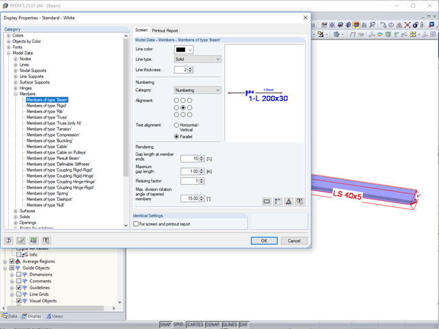
In the case of large models, it is often problematic when the cross‑section descriptions are displayed horizontally or vertically to a member.
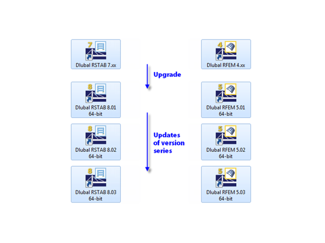
When updating within a version series (for example, RFEM 5.01.01 to 5.01.02), the old program files are removed and replaced by new ones. The project data, of course, remain unchanged. When updating to the next version series (for example, RFEM 5.02.01), the new version is installed in parallel. The program files are located in different directories, so the previous version is still available.

Slender bending beams that have a large h/w ratio and are loaded parallel to the minor axis tend to have stability issues. This is due to the deflection of the compression chord.

Wind blowing parallel to the surfaces of a structure can generate friction forces on these surfaces. This effect is important mainly for very large structures.
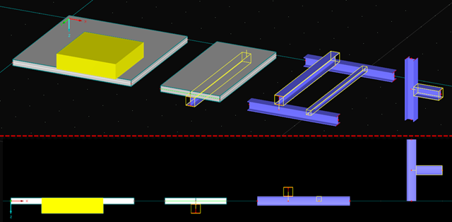
In the case of a parallel offset of the structural plane of members and surfaces and also applying an axial offset to members, for example, the function of eccentricities may be useful.

If you want to connect members tangentially to a curved member or a curved surface in RFEM, it is necessary to define the member rotation of the connected members. In order to avoid manual determination, you can display the center point of the curved line and place a node on it. Then, you can select the "Member Rotation via Help node" option and specify the relevant help nodes. Thus, the members are rotated automatically in the defined plane (x-z in our example) and the top edge of the rotated cross-section is parallel to the tangent of the curved line.
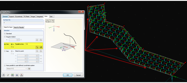
It is often necessary to adjust the FE mesh of surface elements to the geometric structure. RFEM provides various options for this. For example, the FE axis can be rotated around a point, aligned in the direction of a point, or oriented to a user-defined coordinate system. Another option is the direction parallel to a line, and in this case in particular, it is possible to enter or select several lines.